From Crystal Scan to CNC Coring
This user case demonstrates how to go from a crystal scan to generating G-code for CNC coring. It involves preparing the crystal, setting up cores, and creating the necessary G-code for a CNC coring machine.
Steps to Create CNC G-code for Coring
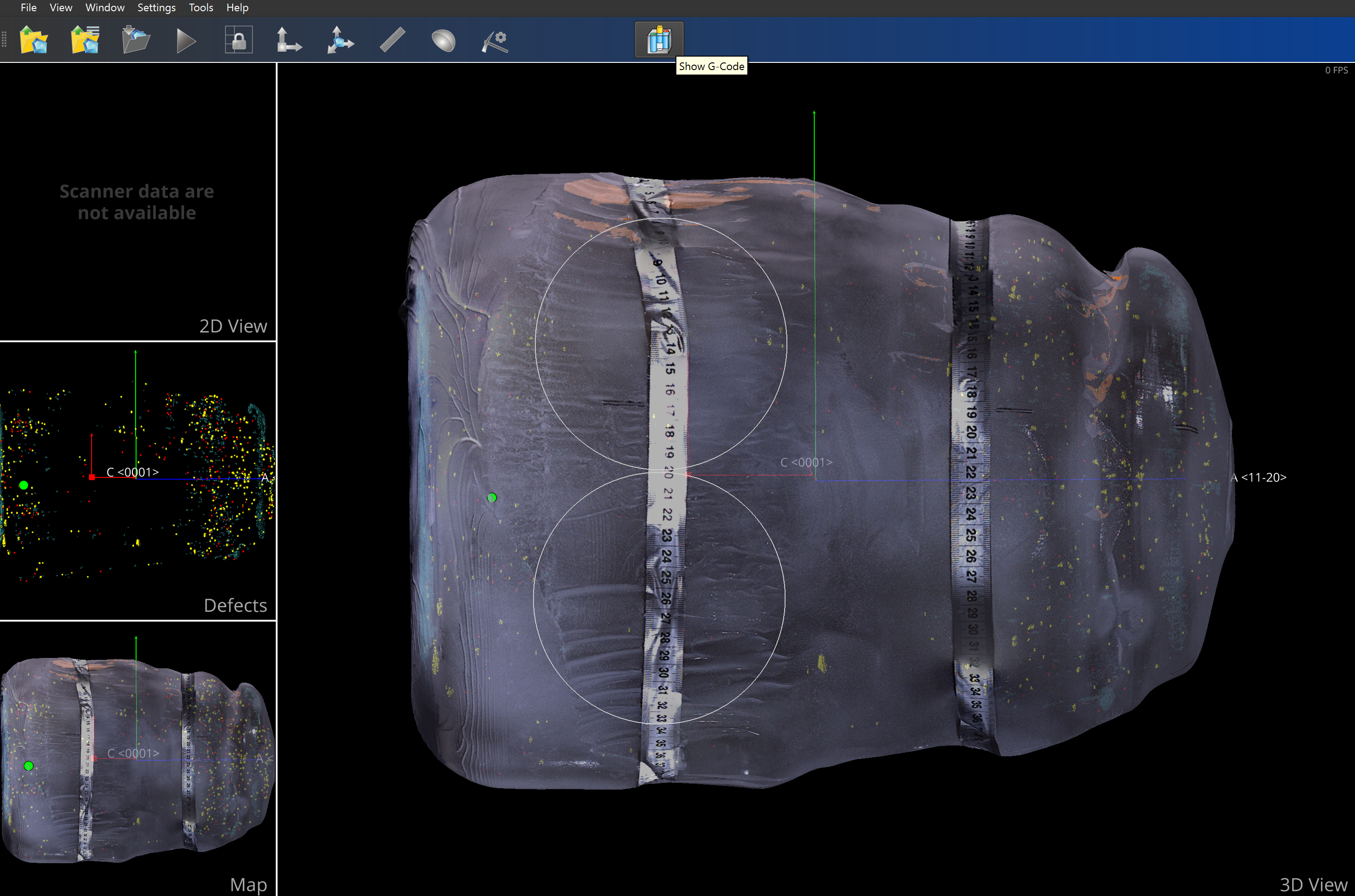
Open Crystal Model: Open the crystal scan model in Yield-Pro. This model will serve as the base for defining the cores and creating the G-code.
Switch to Coring Mode: Navigate to the Coring tab in the software interface. This mode is designed for defining and managing the cores to be cut from the crystal.
Add Cores with Drag & Fix: Use the Drag & Fix feature to add cores to the crystal. Select the desired position on the crystal and drag the tool to adjust its size or orientation. Each core represents a cylindrical section that will be cut during the coring process.
Tip
You can duplicate cores by following the same steps for additional sections.
Calculate Wafers for Each Core: After defining the cores, calculate the wafers for each core to ensure that the setup meets your production requirements.
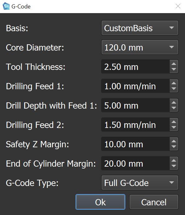
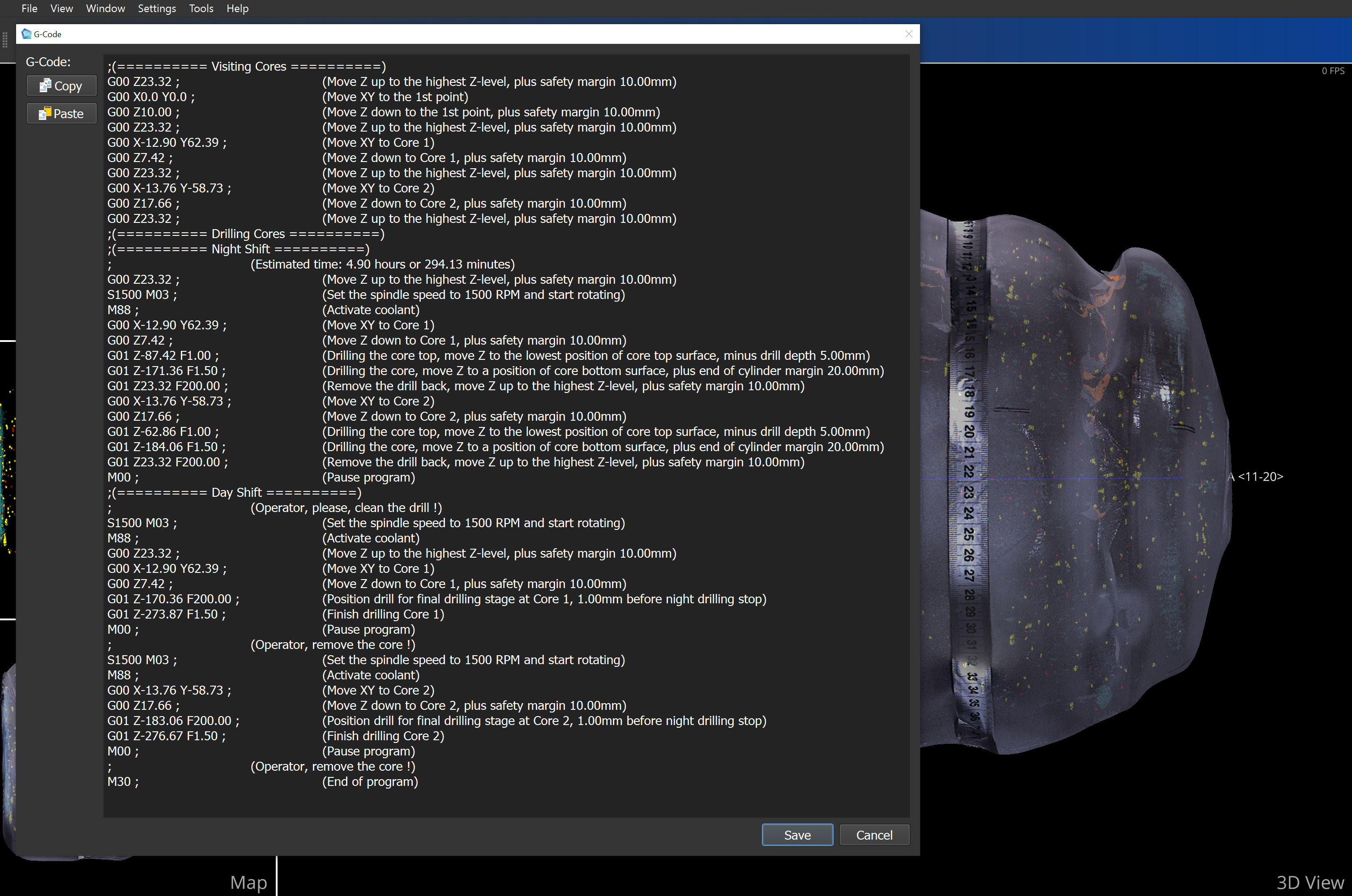
Generate G-Code for CNC: Once the cores and wafers are defined, generate the G-code. This code will instruct the CNC machine on how to cut the cores from the crystal.
Add Basis: Define two points along the axis where the coring will be performed. The basis defines the orientation and reference points for the coring tool.
Generate G-Code for Each Diameter: The software will create separate G-code for each core diameter, ensuring that the correct parameters are passed to the CNC machine.
Load G-Code into CNC Coring System: After generating the G-code, save the file or copy it to the CNC coring system to execute the coring process.


By following these steps, you can efficiently transition from a crystal scan to generating precise G-code for CNC coring.