Chapter 4: References Tab
The References Tab enables you to add or modify visual elements such as points, axes, and other markers on top of the model. It also allows you to manage the visibility of existing reference points and elements.
Reference Elements
In the References Tab, you can manage the following elements:
Points: Add points to the model to mark specific coordinates.
Axis: Create axes for orientation or measurement purposes.
Basis: Define a new basis for the model, which can be useful for aligning or orienting other elements in new coordinates systems.
Planes: Insert reference planes for alignment or advanced measurement tasks.
Each reference element has several attributes:
Key: It is the unique identifier for the element.
Label: A description or name for the reference point, axis or plane.
Type: Specifies whether the element is a point, axis or plane.
Color: Displays the color associated with the element.
Coordinates: The XYZ coordinates of the element in the model.
You can adjust the properties of each reference element, such as its color or label, by clicking on its corresponding field in the table. For example:
To change the color, click the color box and a color picker will appear.
To adjust the label, click on the label text and you can edit it directly.

Managing Reference Elements
In the below list of elements available in the References Tab, you will see several action buttons designed to manage the reference points and other elements.
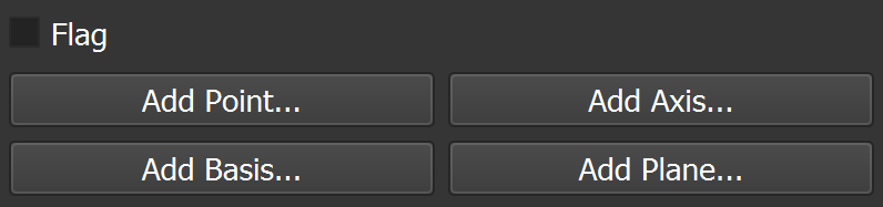
Add Point
Allows you to add new points in the References tab. If a point is not saved as a reference, it will not be retained consistently. There are two available methods for adding a point:
Use Grid and Measurement tool:
Click on
 in the Toolbar.
Double-click on the desired location in the model to place a point.
Click on the
Add Point...button in the References Tab to save the point.Specify the label and color for the point in the dialog that appears.
Click on
Okto add the point to the model.
Use the Add Point button directly:
Click on
Add Point...Specify directly the label, XYZ coordinates and color in the dialog that appears
Click on
Okto add the point to the model.
Add Axis
Allows you to create a new axis in the model. This is useful for defining orientations or directions for measurements. To add an axis:
Click on the
Add Axis...button.
You will have the choices between several Mode:
xyz (space): Defines the new axis based on the actual xyz axes of the model.
Phi: Angle between the X-axis and Y-axis in the XY plane.
Theta: Angle between the Z-axis and the projection of the axis onto the XY plane.
xyz (direction): Defines the new axis based on a direction vector.
Direction: Specifies the direction vector for each axis (X, Y, Z).
End Point: Defines the axis using an end point.
End Point: Specifies the point (a point must be added first) that will be used to define the axis. The axis is created by drawing a line from the origin to the selected endpoint.
Selected Points: Creates an normal axis based on the plane defined by the selected points. At least three points must first be selected in the References tab.
Direction: Specifies the direction of the new axis.
Note
All Mode, also include a Flag field, which allows you to add an additional label to the axis.
Press
Okto add the axis.
Tip
You can view the XYZ axes used in the model by clicking on ![]() in the Toolbar. This displays the three axes (X, Y, and Z) in all four views, positioned in the lower-left corner, to help you understand the model’s orientation. X is shown in red, Y in green, and Z in blue.
in the Toolbar. This displays the three axes (X, Y, and Z) in all four views, positioned in the lower-left corner, to help you understand the model’s orientation. X is shown in red, Y in green, and Z in blue.
Add Basis
Allows you to define a new basis for the model, which is essential for aligning or orienting other elements in new coordinate systems. A basis is a set of reference elements that link the 3D model to the physical crystal positioned in the coring system. To add a basis:
Click on the
Add Basis...button. This action will prompt you to select two reference points within the model.
Select two referenced points in the model that will define the basis:
The Origin point sets the origin of the basis.
The Second point defines the direction of the X-axis.
Select Axis: this should correspond to the Z-axis of the new basis.
Press
Okto create the basis.
Rotate the Model: Once the basis is created, Yield-Pro allows you to rotate the model along the new axis. This helps you visualize the core alignment. Press
7to center the view on the origin point.
Add Plane
Allows you to create a plane from several selected points. To add a plane:
Select at least three points in the model that will define the plane.
Click on the
Add Plane...button.
Specify the label and color for the plane in the dialog that appears.
Press
Okto add the plane to the model.
Action Buttons
At the bottom of the References Tab, the following action buttons are available for working with multiple reference points:
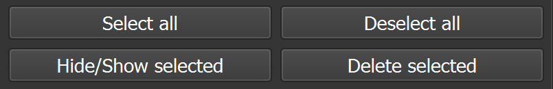
Select All: Highlights all reference points and elements in the list.
Deselect All: Clears any highlighted elements.
Hide/Show Selected: Toggles the visibility of the selected reference points or elements in the model view.
Delete Selected: Permanently remove the selected elements from the model.
Warning
Deleting a reference point or element will remove it permanently from the model, and this action cannot be undone. Use this feature with caution.
Tip
If you want to select several files you can use Ctrl + Click to select multiple elements in the list. This allows you to perform actions on several elements at once, such as hiding or deleting them.