Chapter 6: Coring Tab
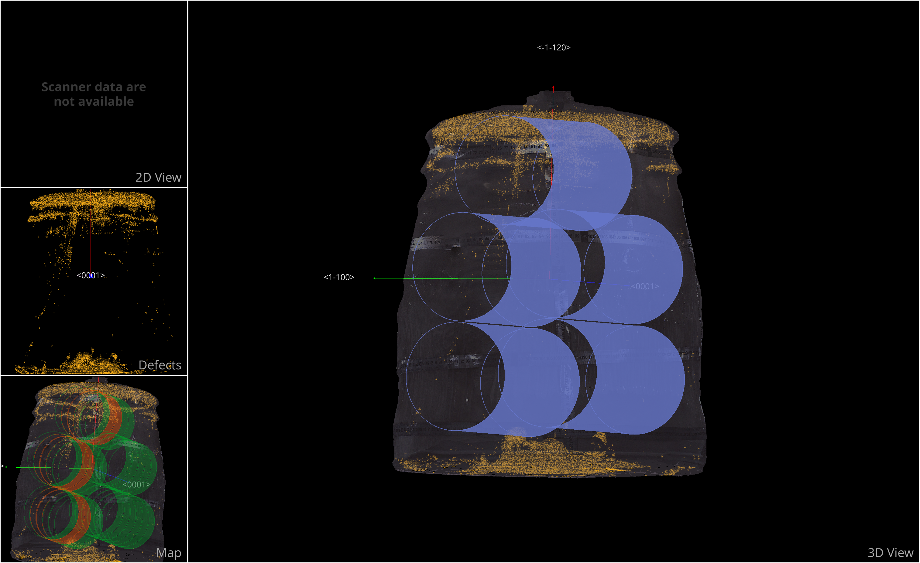
The Coring Tab in Yield-Pro is designed for defining and managing cylindrical cores intended for cutting and further processing. It offers both automatic and manual core creation, along with tools to adjust essential parameters such as core size, position, and orientation.
Core Management Section
This section provides an overview of the coring process, including the available modes and parameters for creating and managing cores.
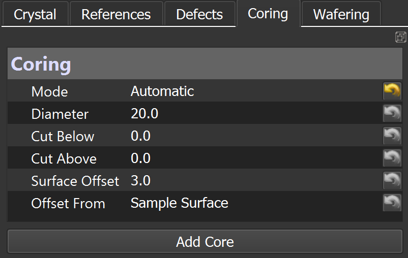
Mode: Select Automatic, Two-Points and Drag-n-Fix Mode for core creation.
Automatic: Creates cores based on predefined parameters, suitable for quick setups.
Cut Below: Defines the depth below which the cut should not proceed (in mm).
Cut Above: Sets the height limit above which the cut should not extend (in mm).
Two-Points: Creates cores by specifying two points in the model, allowing for more precise control over core placement and orientation.
Pt1: The first point defining one extremum of the core.
Pt2: The second point defining the other extremum of the core.
Drag-n-Fix Mode: Allows users to interactively place and adjust cores by dragging them to the desired position on the model.
Axis: Specifies the axis along which the core will be aligned.
Min. Core Length: Sets the minimum length of the core to be created.
Important
Automatic mode works only for cylindrical samples. Drag-n-Fix only for model Mesh Texture.
Warning
Stretch should always be set to True.
Diameter: Specifies the diameter of the core to be created.
Stretch: Adjusts the core's depth to the sample if set to True.
Surface Offset: Adjusts how much of the core surface should be offset from the base sample surface (in mm).
Offset From: Chooses whether the offset is calculated from the sample surface or another reference point.
Tip
Sometimes, Drag-n-Fix mode may already be active by default. If that's the case, make sure to also enable the Grid and Measurement
 tool.
tool.While in Drag-n-Fix mode, press
Ctrl+ Click to confirm and place the core at the desired location.
How to Create a Core
To create a core in the Coring Tab, follow these steps:
Select the Mode: Chooses the desired mode for core creation from the dropdown menu.
Set Parameters: Adjusts the parameters such as diameter, surface offset, and axis according to your requirements.
Create the Core: Click on
Add Corebutton to create the core based on the selected mode and parameters.
Core Parameters
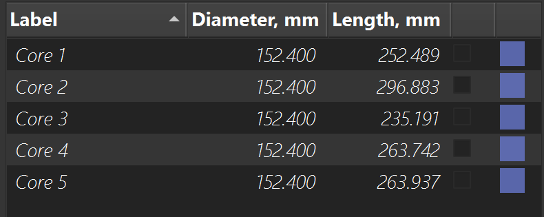
Once a core is created, the following properties can be edited:
Label: A unique identifier for the core.
Diameter: The size of the core in millimeters.
Length: The height of the core in millimeters.
Color: The visual color assigned to the core in the model.
Action Buttons
At the bottom of the Coring Tab, the following action buttons are available:
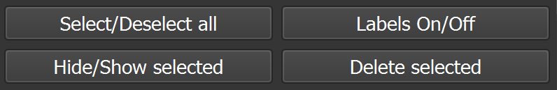
Select/Deselect all: To quickly select or deselect all cores in the list.
Labels On/Off: To show or hide labels for each core.
Hide/Show selected: To hide or display the currently selected cores in the 3D view.
Delete selected: To permanently delete the selected cores from the model. This action is non-reversible, so proceed with caution.