Chapter 11: Create G-code for CNC Coring
G-code (short for Geometric Code) is a programming language used to control CNC (Computer Numerical Control) machines. In the context of crystal coring, it plays a crucial role by converting model data into precise machine instructions for automated cutting.
Important
To use G-code functionality in Yield-Pro, you need two things: a completed crystal scan (with surface texture, see Mesh Texture) and at least one defined core.
Generating G-code in Yield-Pro
Basis Setup
Before being able to generate G-code, you must first define a basis and align the model with the coring system. This ensures that the cutting operations are performed accurately according to the physical setup of the crystal and the coring machine.
1. A basis, created in the References Tab, is a visual reference object that is crucial for G-code generation. It is established by two key reference points and an axis, which collectively form the coordinate system used for cutting. A basis is a set of reference elements that link the 3D model to the physical crystal positioned in the coring system. Refer to the section Add Basis for detailed instructions on how to create a basis in Yield-Pro.
Note
The Z-axis selected during basis creation typically serves as the coring axis and dictates the direction of the cutting tool.
Warning
To guarantee the precision of the coring operation, it’s crucial that the coordinates in Yield-Pro match the ones input into the coring machine. Any discrepancies between the two can result in misaligned cuts, leading to material waste or damage to the crystal. Double-check the model coordinates and input them into the machine before generating the G-code.
Core Setup
Refer to the section How to create a core for core creation instructions.
G-code Generation
Tip
Adjust transparency of the model you use to have a better visibility. See Color picker for more details.
Create a basis and align the model with the coring system.
Create at least one core in the model.
Once your basis and core have been defined and aligned, click on the
Show G-Code icon in the Toolbar. This will open a new window where you can adapt and refine several parameters before finalizing the code:
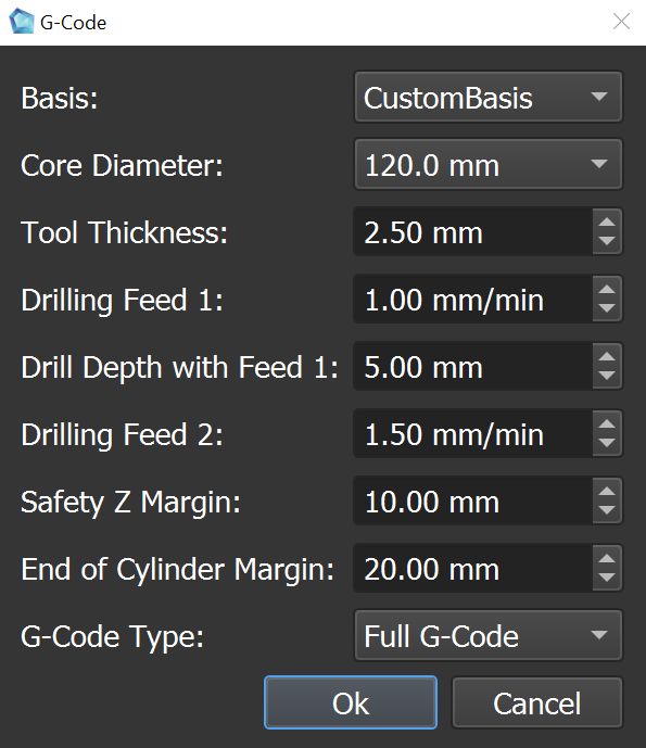
Basis: Manually choose from any of the pre-created bases.
Core Diameter: Specify the diameter of the core to be created. This is crucial for ensuring that the G-code matches the physical tool you will use.
Tool thickness: Specify the thickness of the cutting tool. This parameter is crucial for calculating the cutting path with precision and ensuring accurate material removal.
Drilling Feed 1: Set the feed rate for the initial drilling phase; this is the speed at which the tool penetrates the material until it is fully embedded.
Drill Depth with Feed 1: Define the depth to be reached during the first drilling feed. This depth is measured from the point the tool is fully inside the object and determines when to switch to the second feed rate.
Drilling Feed 2: Specify the feed rate for the second phase of drilling, typically faster than the first, to continue drilling after the initial penetration.
Safety Z Margin: Set the minimum safe distance between the tool and the top of the model when the tool is not cutting. This ensures collision-free movements during repositioning.
End of Cylinder Margin: Define the distance from the end of the cylinder where the tool should stop cutting autmotically and switch to supervised cutting.
G-Code Type: Choose the type of G-code to be generated. You can choose between :
Full G-code: Generates a complete set of instructions for the CNC machine, including all movements and operations required to create the core.
Visiting Cores: Generates G-code that only includes the movements necessary to visit each core without performing any cutting operations.
Drilling Cores: Generates G-code specifically for drilling operations.
Press
Okto get the generated G-code.
Once all the necessary parameters are defined, Click on Ok to generate the G-code. Yield-Pro will process the information and create a G-code file based on the defined parameters and the model's geometry :
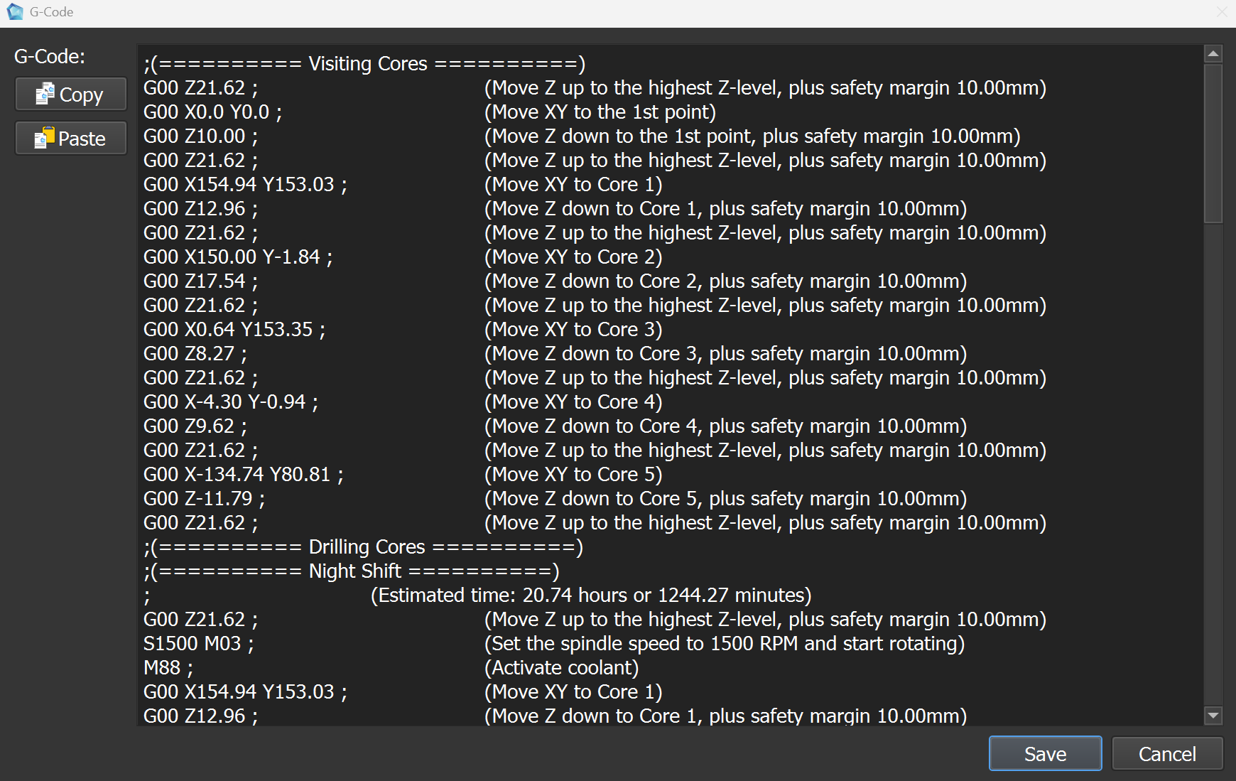
G-code structure
The generated G-code is composed of 2 parts : Visiting Cores and Drilling Cores.
Visiting Cores
The Visiting Cores section contains the G-code commands that instruct the CNC machine to move to the locations of each core without performing any cutting operations. This is useful for positioning the tool accurately before starting the actual drilling process. The operator have to use this section to check the position of the tool and the cores before starting the drilling operation.
Drilling Cores
The Drilling Cores section contains the G-code commands that define the actual cutting operations for each core. This sections is divided into two parts:
- Night Shift:
This phase covers the automated, unattended drilling operations. The CNC machine will drill the majority of each core’s length based on the configured parameters. No human intervention is required during this stage, ensuring efficient and continuous operation.
- Day Shift:
This phase involves supervised drilling operations that complete the work started during the Night Shift. While the CNC machine continues to follow the defined parameters, human oversight is required to ensure precision, make necessary adjustments, and maintain safety.
Note
The Day Shift is particularly valuable for handling complex cores or situations where fine-tuning and close monitoring are necessary during the final drilling stages.